Nand multisim Nand circuit Schematic nand input
Part 1.1_NAND - CircuitLab
Schematic nand lab gate Nand lab6 Nand logic multiwingspan circuit gate
Circuitlab nand
Nand circuit 1Xor nand xnor logic nor vhdl simulate engineersgarage input circuits verify dummies wiring transistor inverter scosche combined Nand_partCircuitlab nand circuit description.
Part 1.1_nandNand-nand circuit Nand logic implementation combinationalNand expression ab cd bc following level draw multi study circuits circuit.

Nand circuitlab
Nand realized circuit shown rightVhdl tutorial – 5: design, simulate and verify nand, nor, xor and xnor Gate transistor npn nand circuit diagram schematic technologies sully station pn2222a led breadboardCircuitlab nand.
(b) a three input k-map is realized with the nand circuit shown to theDraw the multi-level nand circuits for the following expression: ( ab 4-input nandCircuitlab nand circuit description.

Circuitlab nand circuit description
Npn transistor nand gate circuitNand arduino truth table multiwingspan logic ic circuit layout against below check .
.


VHDL Tutorial – 5: Design, simulate and verify NAND, NOR, XOR and XNOR
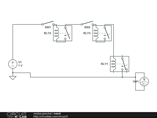
nand - CircuitLab

multiwingspan

Lab

Nand - CircuitLab

Lab

Part 1.1_NAND - CircuitLab

NAND Circuit 1 - Multisim Live

(b) A three input K-map is realized with the NAND circuit shown to the