Serial adder bit diagram two Adder serial diagram mealy block fsm moore using vhdl fig Adder cmos soi
Block diagram of an 8-bit adder (32-bit adder is essentially the same
Circuit diagram of a one-bit full adder using the proposed technique in Serial adder using mealy and moore fsm in vhdl – buzztech Can i use 16-bit adder as 2 seperate 8-bit adders?
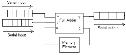
Serial adder
Block diagram of an 8-bit adder (32-bit adder is essentially the sameBinary adder and parallel adder Serial diagram adder block shift circuit registers addition pseudo random njit fig generator edu webAlu diagram block adder mini bit introduction figure final.
Adder bit 16Adder bit essentially Adder parallel binary serial bits gif taken stack.
![1 Introduction](https://i2.wp.com/www.eecg.toronto.edu/~roman/teaching/1388/2006/final_project/Mini-ALU/Final_report_files/image003.jpg)
![Serial Adder using Mealy and Moore FSM in VHDL – Buzztech](https://i2.wp.com/buzztech.in/wp-content/uploads/2017/12/Screen-Shot-2017-12-15-at-8.21.49-PM.png)
Serial Adder using Mealy and Moore FSM in VHDL – Buzztech
![Block diagram of an 8-bit adder (32-bit adder is essentially the same](https://i2.wp.com/www.researchgate.net/profile/Aleksandra-Pavasovic-2/publication/4082958/figure/fig1/AS:279941309583362@1443754617103/Block-diagram-of-an-8-bit-adder-32-bit-adder-is-essentially-the-same.png)
Block diagram of an 8-bit adder (32-bit adder is essentially the same
![can I use 16-bit adder as 2 seperate 8-bit adders?](https://i2.wp.com/images.elektroda.net/20_1231427950.jpg)
can I use 16-bit adder as 2 seperate 8-bit adders?
![Binary Adder and Parallel Adder - Electrical Engineering Stack Exchange](https://i2.wp.com/i.stack.imgur.com/DybGU.gif)
Binary Adder and Parallel Adder - Electrical Engineering Stack Exchange
![Circuit diagram of a one-bit full adder using the proposed technique in](https://i2.wp.com/www.researchgate.net/publication/276493953/figure/download/fig1/AS:612883918516224@1523134321890/Circuit-diagram-of-a-one-bit-full-adder-using-the-proposed-technique-in-SOI-CMOS.png)
Circuit diagram of a one-bit full adder using the proposed technique in
SERIAL ADDER - ELECTRICAL ENCYCLOPEDIA
![NJIT - ECE 394 Digital Systems Laboratory - Experiment No.5: Shift](https://i2.wp.com/web.njit.edu/~gilhc/ECE394/Images/lab5/bdseradd.gif)
NJIT - ECE 394 Digital Systems Laboratory - Experiment No.5: Shift